An RF shielding test needs a project-specific performance schedule. The schedule should identify frequency, required attenuation, field regime, polarization where applicable, test locations and the agreed method. There is no single attenuation limit that should be applied to every SCIF or SAPF.
What shielding-effectiveness testing establishes
RF shielding effectiveness describes the reduction in electromagnetic field or received signal level associated with a shielded enclosure under a defined measurement arrangement. Results are normally expressed in decibels at specified frequencies. Testing relies on a documented reference condition, the selected antennas or probes, suitable transmitter and receiver settings, and measurements made with the shielding boundary in its agreed installed condition. A quoted attenuation value without its frequency, location, reference arrangement and measurement limit is insufficient for a defensible acceptance comparison.
Measurement capability must be considered before testing. If the received signal falls below the practical system noise floor or becomes indistinguishable from ambient RF, the result may establish only a supported minimum demonstrated attenuation, not an exact higher value. The final report should make that distinction explicit. IEEE 299 measurement planning and the pre-mobilization checklist explain the applicable method and reporting decisions.
Create a frequency-and-location matrix
| Scope element | Decision required |
|---|---|
| Frequency and regime | What range and field conditions are relevant to the approved requirement? |
| Performance limit | What shielding effectiveness is required at each specified condition? |
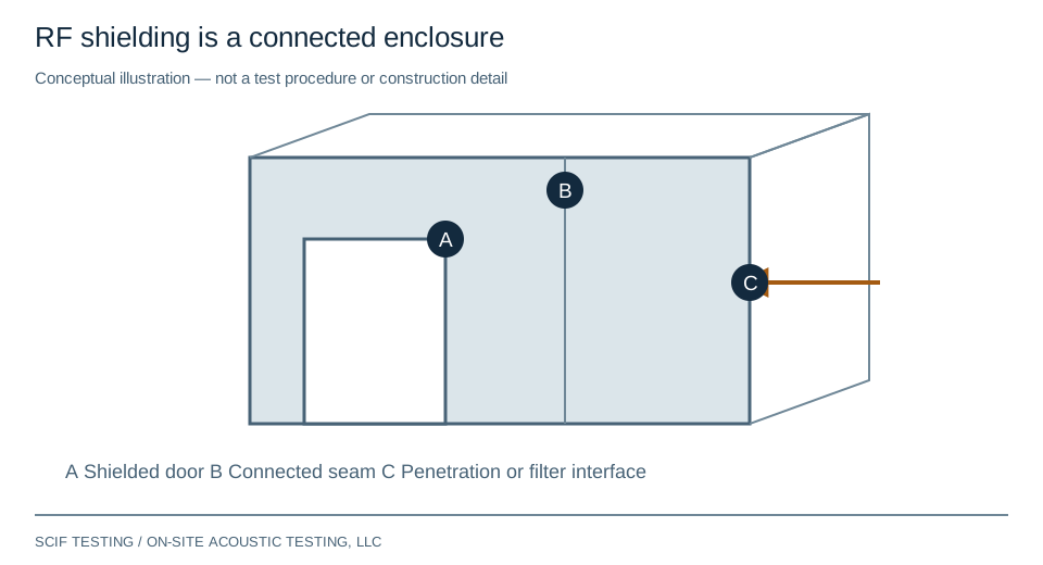
| Locations | Which doors, seams, penetrations and enclosure surfaces are covered? |
| Measurement capability | Can the proposed system demonstrate the requirement above its practical noise and leakage limits? |
Make limitations explicit
Instrument specifications alone do not establish usable on-site measurement range. Ambient signals, receiver noise, reference level, cable coupling and the test arrangement affect the result. A signal below the measurement floor may support a qualified lower bound, but not an arbitrary exact attenuation value.
How to read an RF shielding field result
A usable result is a measurement record, not just a single attenuation figure. The minimum context needed to interpret each reported location is shown below.
| Report field | Why it matters |
|---|---|
| Frequency and test arrangement | Shielding effectiveness is frequency- and setup-dependent; identify antenna/probe arrangement, polarization or field orientation when applicable, and method edition. |
| Reference level | Documents the unshielded or otherwise prescribed reference condition used for the attenuation comparison. |
| Measured level and usable range | Establishes whether the signal was distinguishable from ambient RF, instrument noise and unintended coupling. |
| Result and reporting qualifier | Distinguishes a measured value from a minimum demonstrated value such as “at least X dB” when limited by the measurement floor. |
| Required limit and disposition | Compares the supported result with the project-specified criterion at that frequency and location; records failures or inconclusive evidence. |
For example, if the protected-side signal is below the verified measurement floor, it is not defensible to report an arbitrarily larger shielding value. The report should state the supported lower bound and the limiting condition. Where the test specification requires more demonstrable attenuation than the setup can resolve, the team must change the measurement arrangement or agree a documented disposition rather than assume a pass.
See the IEEE 299 method and edition guide and the RF test-plan checklist. The IEEE Standards Association catalog identifies the status and scope of IEEE 299-2006; a draft revision project is not itself a published replacement.
Keep the conclusion within the measured scope
The report should state the method and edition, enclosure condition, reference measurements, test geometry, locations, frequencies and acceptance comparison. A low-resistance continuity check is useful construction evidence but is not a substitute for RF attenuation measurements. Routine shielding measurements also do not constitute TEMPEST certification.
For projects requesting IEEE 299, review method applicability and edition status before freezing the test plan.
Plan each part of the RF verification
- Pre-mobilization checklist — Agree criteria, frequencies, access and reporting before travel.
- Doors, seams and penetrations — Keep an interface register tied to the enclosure boundary.
- Materials and construction — Review substitutions and installed interfaces beyond a material rating.
- Construction hold points — Inspect and test while interfaces remain accessible.
- Leakage investigation — Separate enclosure findings from measurement limitations.
- Repair and retest coverage — Define what must be measured again after corrective work.
- Periodic verification of existing SCIFs — Consider whether changes since commissioning warrant renewed acoustic or RF measurements.
For Special Access Program Facilities, see SAPF testing and authority-specific RF requirements.
For an initial scope discussion, request testing using unclassified information only. OSAT documents measured performance; the responsible authority makes acceptance and accreditation decisions.